 Original Article

Affiliation:
1Department of Prosthodontics, Mashhad University of Medical Sciences, Mashhad 9177948959, Iran
ORCID: https://orcid.org/0000-0001-5694-3823
Affiliation:
2Department of Endodontics, Dental Clinical Research Development Unit, Birjand University of Medical Sciences, Birjand 1713643135, Iran
Email: sdent22@gmail.com
ORCID: https://orcid.org/0000-0003-1804-5242
Explor Med. 2025;6:1001284 DOI: https://doi.org/10.37349/emed.2025.1001284
Received: September 22, 2024 Accepted: December 25, 2024 Published: February 18, 2025
Academic Editor: Gaetano Isola, University of Catania, Italy
Aim: This study compared curved canal’s apical transportation by using Neoniti A1 with/without Neoniti C1 using cone-beam computed tomography (CBCT).
Methods: This experimental in vitro study was conducted to analyze the mesiobuccal canals of extracted mandibular and maxillary molars (n = 62) with 20°–40° curvature. After determining the length of the roots, they were mounted in a custom-made holder and randomly sorted into two groups (n = 31). The roots underwent preoperative CBCT. Root canals in group 1 were only remodeled using the Neoniti A1 file while in group 2, the coronal third of the root canals was first prepared with Neoniti C1, and then the remaining part of the canal was instrumented with Neoniti A1. CBCT images were obtained again, and the preoperative and postoperative CBCT scans were compared using Romexis software to determine canal transportation at 3 mm, 5 mm, and 7 mm from the apex. Data analysis was done using SPSS 18.
Results: Canal transportation was lower in the C1 + A1 group compared with the A1 group at all levels, but not significantly (P > 0.05). Canal transportation in both groups was < 0.03 mm at all levels from the apex. In the C1 + A1 group, canal centering was more elevated compared to the A1 group and at 3 mm from the apex, the two groups experienced a significant difference in centering ratio (P = 0.013).
Conclusions: The use of Neoniti A1 files alone does not increase canal transportation in curved canals; however, the centering ability was higher in the use of C1 + A1. Therefore, coronal flaring is suggested.
The success of root canal treatment is dependent on cleaning and shaping the root canal system (RCS) as an important step. It also affects the efficacy of root canal irrigation and the quality of obturation. An instrumented canal should have a uniform conical shape with decreasing diameter from the coronal towards the apical region, providing adequate space for the activity of irrigating solutions [1]. Preserving the original canals and root structure is crucial for successful root canal preparation [2]. Instrumentation is more challenging in severely and abruptly curved root canals [3].
This is done by enlarging and shaping the canal to allow for adequate chemical debridement while preserving the radicular anatomy.
It is particularly difficult to instrument the apical third due to its complexity both in canal shape and in ramification [1, 4]. Regardless of the instrumentation technique, cleaning and shaping procedures inevitably lead to dentin removal from the canal walls. However, excessive dentin removal in a single direction within the canal rather than in all directions equidistant from the main tooth axis causes what is known as canal transportation [5, 6]. Apical transportation can cause the apical foramen to move from its anatomical position to an iatrogenic position in the root canal wall, causing further aggravation and causing treatment failure [7]. Apical transportation is responsible for impairing the root structure’s integrity, decreasing its fracture resistance, and leading to perforation of root canal walls when using larger files [5].
Innovative nickel-titanium (NiTi) instruments have been developed to enhance the efficacy of root canal treatment. The use of more flexible NiTi rotary files instead of stainless-steel hand files can reduce canal transportation and errors [8]. Improvements in mechanical properties of endodontic files focused on properties like cutting efficiency, flexibility, and fracture resistance.
Due to their higher flexibility, NiTi files can reduce the risk of procedural errors in narrow curved canals [9]. Thus, they can preserve the canal shape and decrease canal transportation. In NiTi files, deformation can be reversed up to 10%, while conventional alloys only have a maximum rate of 1%. Moreover, NiTi files have lower wear and deformation than stainless steel (SS) files and have excellent anti-corrosive properties as well [10].
The Neoniti (Neolix, Châtres-la-Forêt, France), which is introduced as a single file rotary system, is manufactured from the heat-treated wire alloy which provides these files with cyclic fatigue resistance and controlled memory, improving their canal preservation properties [11]. In addition, The electrical discharge machining (EDM) technology produces a rough surface, which improves their abrasiveness and cutting efficiency [6, 12, 13].
Neoniti contains a heterogeneous rectangular cross-section and multiform tapers in a single file that contains a C1 file as an orifice shaper (with size 25#, taper at the tip of 0.12 mm and length of 15 mm) and three A1 (with #20, #25 and #40 tip sizes) instruments [14].
Various techniques are employed to evaluate the effectiveness of NiTi files in preserving the original path of the central canal. These methods include radiography, sectioning as per Bramante’s technique, longitudinal tooth clearing, high-resolution computed tomography (CT), micro-CT, and cone-beam CT (CBCT) [15–17]. CBCT is an effective method for measuring dentine thickness, canal transportation, and centering ability used in many recent studies [18, 19]. CBCT is known for its high-resolution imaging capabilities, making it ideal for assessing root canal morphology, detecting fractures, and observing alterations in the RCS after preparation [20].
In this study, CBCT was chosen for its non-invasive nature, allowing for precise and repeatable three-dimensional evaluations at a smaller field of view of the RCS without causing damage to the specimens [7]. On the other hand, information regarding apical transportation and centering ability following root canal instrumentation with Neoniti A1 with/without Neoniti C1 is limited; therefore, this study’s objective was to evaluate these two features in curved root canals using CBCT.
This experimental in vitro study was conducted to analyze the mesiobuccal canals of extracted mandibular and maxillary molars (n = 62) that had been extracted due to poor periodontal prognosis, endodontic problems with hopeless prognosis, or as part of the orthodontic treatment plan.
Periapical radiographs were obtained using a computed radiography (Digora, Soredex, Helsinki, Finland). Angles and radius of canal curvatures were measured using the Schneider method [21] and a modified Pruett method [22]. Inclusion criteria were: sound root with moderate to severe angles of curvature 20° < α < 40°. Exclusion criteria included dental anomalies, prior root canal treatments, root caries, root fractures, root resorption, or calcification that could not be negotiated with a #10 K-file (maximally) and 19–22 mm length.
According to a study by Madani et al. [7], assuming a type 1 error of 0.05, study power of 80%, and precision of 0.08, there were 54 teeth in the sample, with 27 in each group. By considering the attrition rate of 15%, the final sample size was calculated as 62 teeth (31 teeth in each group).
To balance the number of samples allocated to each of the study groups, the eligible teeth were divided into two groups in the randomized block sampling method. Five blocks of 6 and 1 block of 2 were created with different and random combinations in terms of the order of 2 letters A (Neoniti C1) and 2 letters B (Neoniti A1). Block of 2 contains one letter A and one letter B. Then, at each stage, based on the table of random numbers, a block was randomly selected, and based on it, teeth were assigned to one of the two study groups. This process continued until the sample size was completed.
Water was used to rinse the collected teeth, and a plastic brush was used to remove tissue residue. The teeth were then immersed in sodium hypochlorite (2.5%, Tizpak, Tehran, Iran) for 2–3 h for disinfection and stored in saline at 4°C until the experiment.
The distal and palatal roots of the maxillary molars and the distal root of the mandibular molars were cut at the furcation area by using a high-speed hand-piece (NSK, Tokyo, Japan) and a diamond bur under water irrigation. Next, a #10 K-file (Mani, Tokyo, Japan) was introduced into the canal until its tip was visible at the apex. The working length was determined 1 mm shorter. In the maxillary molars, the mesiolingual canal was ignored. The teeth were randomly divided into two groups (n = 31) and were mounted in custom-made horseshoe-shaped arch in a standard vertical and horizontal position such that the occlusal surface of the teeth was positioned horizontally, and the buccal surface was parallel to the anterior surface of the molds. Four holders were designed with a 7 mm length in the form of a dental arch. Two holders contained 16 teeth and 2 others had 15 teeth. To ensure that the plaster’s opacity did not diminish image clarity, the teeth were mounted in wax molds using white dental stone and sawdust in equal proportions. This was done to simulate the jawbone in CBCT. Before root canal instrumentation, all roots underwent CBCT (Quantitative Radiology SRL Co., Verona, Italy) by oral, maxillofacial radiologist. A #15 SS K-file was used to the working length to create a glide path. In group 1, Neoniti C1 (Neolix, Châtres-la-Forêt, France) was used for flaring of the coronal third and then Neoniti A1 (Neolix, Châtres-la-Forêt, France) was used for the working length of the root canal instrumentation. In group 2, root canals were prepared with Neoniti A1 file alone to the working length. RC Prep (Meta Biomed, Cheongju-si, Korea) was used as a lubricant in both groups. Also, root canals were rinsed with sodium hypochlorite (2.5%, Tizpak, Tehran, Iran) in both groups. For this study, Neoniti files were used along with Endo-Mate DT motor (model number DT-123, 100–40,000 RPM, 0.5–4.0 Ncm torque, NSK, Japan). The files were used with gentle in-and-out and brushing motion according to the manufacturer’s instructions. The C1 file (#25, 0.12% taper) was used for the instrumentation of the coronal third and the A1 file (#25, 0.08% taper) was used for the working length for the instrumentation of the entire root canal length.
The procedures were carried out by a trained senior dental student under the supervision of an associate professor of endodontics for two study groups. After root canal preparation, the root canals underwent CBCT again with the same parameters as the baseline CBCT. The images were evaluated in Romexis imaging software (version 3.8.2.R, Planmeca) on a 32-inch monitor in dim light (Figure 1).
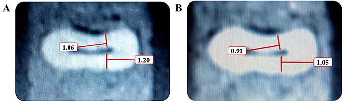
Cross-sectional measurements made on cone-beam computed tomography (CBCT) micrographs. The dentin thickness of the root has been measured (A) before and (B) after root canal instrumentation at 7 mm from the apex on CBCT
On each CBCT section, the minimum distance between the internal and external surface of the root canal was measured at 3 mm, 5 mm, and 7 mm from the apex. The measurements were made with 0.01 mm accuracy. The amount of canal transportation and centering ratio were calculated separately at 3 mm, 5 mm, and 7 mm levels from the apex using the following formula:
(M1 – M2) (D1 – D2) where D is the shortest distance between the internal and external surfaces of the distal canal wall (thickness of distal canal wall) and M is the shortest distance between the internal and external surfaces of the mesial canal wall (thickness of mesial canal wall). The amount of dentin removal from the root canal was specified in cubic millimeters (mm3). Precise measurements before and after instrumentation indicated the amount of removed dentin from the mesial and distal canal walls. Thus, the result of zero in the formula indicated no canal transportation. Larger values indicated greater canal transportation and smaller values indicated a lower amount of canal transportation. To assess the centering ratio, the formula (M1 – M2) (D1 – D2) was used. In this formula, a result of 1.0 indicated high centering ability. Figure 2 shows the schematic view of the calculation of canal transportation and centering ratio.
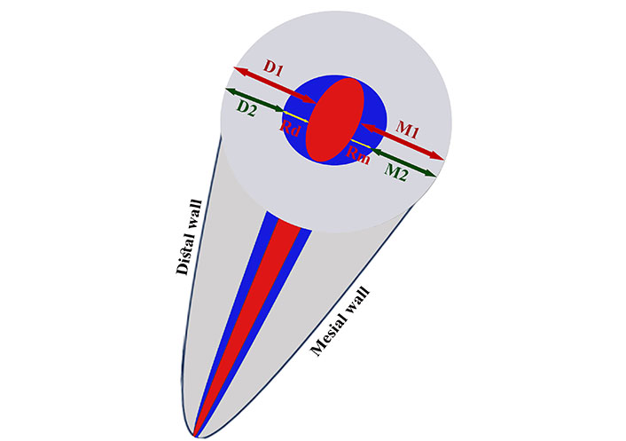
Schematic view of canal transportation and canal centering. The red small oval shape at the center indicates the un-instrumented canal. The blue circle indicates the instrumented canal. D1 and M1 are the width of distal and mesial root canal walls before instrumentation, respectively and D2 and M2 indicate the width of distal and mesial root canal walls after instrumentation, respectively. Rd and Rm indicate the amount of removed debris from the distal and mesial walls, respectively: Rm = M1 – M2, Rd = D1 – D2; degree of canal transportation = Rd – Rm; canal centering ratio = Rd ÷ Rm or Rm ÷ Rd
SPSS-18 software (SPSS Inc, Chicago, IL, United States) was used to analyze the data. Data distribution normality was evaluated using the Kolmogorov-Smirnov test. Independent samples t-test (data with normal distribution) and Mann-Whitney test (data with non-normal distribution) at significant level α = 0.05 were used for data analysis based on the Kolmogorov-Smirnov test results.
As shown in Table 1, the mean dentin thickness of the distal wall at 3 mm distance from the apex was lower than that at 5 mm and 7 mm from the apex, with no significant differences between the two groups (P > 0.05). Statistically, there was no significant differences in the dentin thickness of mesial and distal canal walls at different levels from the apex between the two groups (P > 0.05).
Mean dentin thickness in the mesial and distal canal walls in the two groups prior to instrumentation
| Group | Mean(mm) | SD(mm) | T-test statistic | Df | P-value | Effect size (Cohen’s d) | |
|---|---|---|---|---|---|---|---|
| Mesial wall, 3 mm | A1 | 0.9481 | 0.19373 | –1.547 | 60 | 0.127 | 0.393 |
| C1 + A1 | 1.0277 | 0.21136 | |||||
| Mesial wall, 5 mm | A1 | 1.0484 | 0.23752 | 0.300 | 60 | 0.766 | –0.076 |
| C1 + A1 | 1.0326 | 0.17293 | |||||
| Mesial wall, 7 mm | A1 | 1.1232 | 0.23624 | –0.137 | 60 | 0.891 | 0.035 |
| C1 + A1 | 1.1310 | 0.20652 | |||||
| Distal wall, 3 mm | A1 | 0.9097 | 0.19663 | –0.982 | 60 | 0.330 | 0.249 |
| C1 + A1 | 0.9619 | 0.22164 | |||||
| Distal wall, 5 mm | A1 | 1.0081 | 0.22716 | –0.041 | 60 | 0.968 | 0.010 |
| C1 + A1 | 1.0103 | 0.20819 | |||||
| Distal wall, 7 mm | A1 | 0.9997 | 0.19570 | –0.781 | 60 | 0.438 | 0.198 |
| C1 + A1 | 1.0400 | 0.21055 | |||||
SD: standard deviation; Df: degree of freedom
Table 2 compares the mean dentin thickness in the mesial and distal canal walls in the two groups after instrumentation. As shown, the mean dentin thickness of the mesial and distal canal walls after instrumentation was slightly higher in the C1 + A1 group than in the A1 group at all levels from the apex; however, at different levels from the apex, the differences between the two groups were not significant (P > 0.05). The mean amount of dentin removed from the mesial and distal canal walls was not significantly different between the two groups at different levels from the apex (P > 0.05, Table 3).
Mean dentin thickness in the mesial and distal canal walls in the two groups after instrumentation
| Group | Mean(mm) | SD(mm) | T-test statistic | Df | P-value | Effect size (Cohen’s d) | |
|---|---|---|---|---|---|---|---|
| Mesial wall, 3 mm | A1 | 0.8042 | 0.20879 | –1.630 | 60 | 0.108 | 0.414 |
| C1 + A1 | 0.8955 | 0.23167 | |||||
| Mesial wall, 5 mm | A1 | 0.8684 | 0.22259 | 0.050 | 60 | 0.960 | –0.013 |
| C1 + A1 | 0.8658 | 0.17780 | |||||
| Mesial wall, 7 mm | A1 | 0.9194 | 0.21409 | –0.142 | 60 | 0.888 | 0.036 |
| C1 + A1 | 0.9265 | 0.17779 | |||||
| Distal wall, 3 mm | A1 | 0.7987 | 0.16134 | –0.428 | 60 | 0.670 | 0.109 |
| C1 + A1 | 0.8187 | 0.20394 | |||||
| Distal wall, 5 mm | A1 | 0.8726 | 0.19676 | 0.636 | 60 | 0.527 | –0.162 |
| C1 + A1 | 0.8403 | 0.20284 | |||||
| Distal wall, 7 mm | A1 | 0.7816 | 0.18657 | –0.951 | 60 | 0.345 | 0.242 |
| C1 + A1 | 0.8281 | 0.19774 | |||||
SD: standard deviation; Df: degree of freedom
Mean amount of dentin removed from the mesial and distal canal walls in the two groups at different levels from the apex
| Group | Mean(mm) | SD(mm) | T-test statistic | Df | P-value | Effect size (Cohen’s d) | |
|---|---|---|---|---|---|---|---|
| Dentin removed from mesial wall at 3 mm | A1 | 0.1439 | 0.07370 | 0.522 | 60 | 0.604 | –0.132 |
| C1 + A1 | 0.1323 | 0.09969 | |||||
| Dentin removed from mesial wall at 5 mm | A1 | 0.1800 | 0.12204 | 0.435 | 60 | 0.665 | –0.109 |
| C1 + A1 | 0.1668 | 0.11751 | |||||
| Dentin removed from mesial wall at 7 mm | A1 | 0.2039 | 0.09996 | –0.024 | 60 | 0.981 | 0.006 |
| C1 + A1 | 0.2045 | 0.10945 | |||||
| Dentin removed from distal wall at 3 mm | A1 | 0.1255 | 0.15205 | –0.464 | 60 | 0.644 | 0.118 |
| C1 + A1 | 0.1432 | 0.14869 | |||||
| Dentin removed from distal wall at 5 mm | A1 | 0.1355 | 0.12490 | –1.051 | 60 | 0.298 | 0.267 |
| C1 + A1 | 0.1700 | 0.13362 | |||||
| Dentin removed from distal wall at 7 mm | A1 | 0.2181 | 0.12584 | 0.204 | 60 | 0.839 | –0.053 |
| C1 + A1 | 0.2119 | 0.10974 | |||||
SD: standard deviation; Df: degree of freedom
The mean amount of canal transportation was lower in the C1 + A1 group at all levels from the apex but not significantly (P = 0.431 at 3 mm, P = 0.257 at 5 mm, and P = 0.864 at 7 mm).
The Mann-Whitney test showed that the centering ratio in the C1 + A1 group was higher than that in the A1 group; this difference was significant at 3 mm from the apex (P = 0.013) but not at 5 mm (P = 0.168) or 7 mm (P = 0.704) from the apex.
This study compared the apical transportation and centering ability of curved canals instrumented with Neoniti A1 single-file system with/without pre-flaring with Neoniti C1 using CBCT. The mesial and mesiobuccal roots of molar teeth with an apical size corresponding to a #10 K-file were used in this study to better simulate the use of rotary files in the clinical setting; because in oval canals, the file is engaged with the canal wall in narrower diameter of the canal, and does not engage with all root canal walls equally [23]. The present results indicated that both groups showed some degree of apical transportation. Canal transportation was lower in the C1 + A1 group compared with the A1 group at all levels, although the difference was not statistically significant. In other words, coronal flaring of the canals before instrumentation had no significant effect on the occurrence or amount of apical transportation. Although the C1 + A1 group showed superior centering ability at 3 mm from the apex.
Glossen et al. [24] reported similar results. They manually prepared the root canals by the balanced force technique and reported that although primary flaring enhanced root canal instrumentation, it had no significant effect on canal transportation [24]. Uzunoglu and Turker [25], Fallatah and El Sherief [26], and Türker and Uzunoğlu [27] found no significant difference in canal transportation between different groups at different levels from the apex, which was in line with the present results. Zanette et al. [18] used the ProTaper Next file with and without creating a glide path and found no significant difference in the amount of canal transportation between the two groups.
Due to the advantages of the Neolix files, such as high flexibility, having a non-cutting tip, positive rake angle, and lower screw-in forces (which is an unfavorable property of rotary files especially in high tapers), canal transportation in both groups in the present study was < 0.03 mm. The greater the amount of canal transportation from 0.03 mm, the poorer the prognosis of treatment would be. Uzunoglu and Turker [25] used One Single Shape and ProTaper Next rotary systems and showed that canal transportation was < 0.03 mm in both groups, which supported the present findings.
In the present study, the minimum amount of canal transportation was recorded at 5 mm (0.0032), 7 mm (0.0074), and 3 mm (0.0110) from the apex in the C1 + A1 group. In the present study, the amount of canal transportation at 5 mm from the apex in the A1 group (0.0445) was higher than that in the C1 + A1 group (0.0032), which indicates greater transportation at the danger zone in the A1 group. It should be noted that most NiTi instruments are used with the crown-down technique such that the thicker part of the file is engaged in the coronal part of the canal before reaching the apical region, and interferences are eliminated as such. Accordingly, the risk of canal transportation decreases. However, the file fatigue increases as such, and the clinical service of the file is compromised. To overcome this problem, it may be useful to use lubricants for real-time torque generated during intracanal instrumentation [28].
The glide path and coronal flaring were advised to use especially in curved root canals to reduce procedural errors such as ledging and file breakage, in contrast, excessive removal of dentin during coronal flaring may result in weakening the root structure, strip perforation, predisposing teeth to fracture, and treatment failure [21].
AbuMostafa et al. [29] concluded that glide path and coronal flaring had an insignificant effect on the dentin volume removal and percentage of untouched walls in curved canals. Hawi et al. [30] reported that coronal flaring could be clinically useful in increasing the centering ability, especially of the austenitic files in the apical third.
According to the present results, the centering ratio was higher in the C1 + A1 group than in the A1 group at all levels from the apex but this difference was only significant at the 3 mm level (P = 0.013). Also, the maximum centering ratio was noted in the C1 + A1 group at the apex (0.37).
Selvakumar et al. [19] compared the centering ratio in three groups K3 file with 0.02% taper, K3 file with 0.04% taper, and SS K file. They reported a higher centering ratio in group 1 and at the apex (1 ± 0.22 mm). Despite the use of different files and methodologies, their results were under the present findings. Schäfer and Zapke [31] reported that the centering ratio of K3 files was much higher than that of K FlexoFiles. Canoglu et al. [23] found no significant difference in the centering ratio of rotary and hand files in any part of the root, which was different from the present results.
A study by Yamamura et al. [32] does not support the use of one rotary file system over the other when comparing transportation and centering ability.
The current study found no significant difference in the mean dentin thickness before instrumentation, the amount of removed dentin, and the final dentin thickness of the mesial and distal canal walls between the two groups at any level from the apex. This finding was in line with that of Mohammadzade Akhlaghi et al. [33], and Garala et al. [34]. In the present study, the maximum amount of residual dentin in both groups was noted at the distal wall at 7 mm from the apex. So, it could be suggested to use this single-file system to shape the curved canals, decrease the incidence of instrument separation, and straighten canal curvature, changing in wall and time-saving [14].
Use of CBCT, evaluation of natural teeth (which increases the generalizability of the results to the clinical setting), and use of white dental stone and sawdust for mounting of the teeth (for repeatability and simulation of the jawbone on CBCT scans) were among the strengths of this study. CBCT allows multiple imaging before and after root canal instrumentation although the resolution of this tool is lower than the one of micro-CT [35]. In addition, the micro-CT imaging technique, despite its higher resolution, is well known to be time-consuming and expensive, especially for a high number of samples [36]. Two approaches are utilized to measure canal transportation using CBCT scans. Some research has involved overlaying pre- and postoperative images to identify alterations in the canal path resulting from the preparation process [37]. Other studies have calculated the distance between the external surface of the root and the internal canal wall at both the mesial and distal sides using pre- and postoperative cross-sectional images at three specific levels. Relevant formulas were then applied to quantify the changes in the canal path [38]. Our study adopted this latter method, measuring the distance from the external root surface to the internal root canal wall at three points (1 mm, 3 mm, and 7 mm from the apex) to assess changes in the apical and middle thirds of the root canal, as these areas are more prone to procedural errors.
Despite the attempts to standardize the teeth, extracted teeth cannot be perfectly standardized in terms of canal size and root curvature, which was a limitation of the present study. Further studies are required to compare different rotary files and also with hand files regarding apical transportation with/without pre-flaring.
Many factors can affect shaping ability including instrument size and taper, as well as the design and type of alloy [30]. Also, anatomical complexities need to be evaluated in clinical conditions [39]. As well as evaluation of cyclic fatigue with and without coronal flaring that impacts on life span of the files [40]. Further studies (in vitro and in vivo) are warranted to confirm and generalize these results. In a systematic review aimed at answering the question of whether the use of martensitic root canal instruments could result in less apical transport compared to austenitic instruments during root canal therapy, they concluded that martensitic root canal instruments had less apical transport than austenitic instruments during the shaping phase of root canal therapy, and this behavior could be attributed to the increased flexibility of martensitic instruments. Although, they considered that further research is necessary to provide additional evidence to support the use of martensitic instruments in clinical practice [41].
Another limitation of this study is the limited sample size. Conducting the study with a large sample size is needed to confirm the study results.
Comparable minimal apical transportations were demonstrated using the two methods of preparation. However, the centering ability was better in the use of C1 + A1, therefore, coronal flaring might be suggested.
CBCT: cone-beam computed tomography
CT: computed tomography
NiTi: nickel-titanium
RCS: root canal system
SS: stainless steel
The authors would like to thank the Vice-Chancellor for Research of Birjand University of Medical Sciences for their support and cooperation.
SE: Conceptualization, Methodology, Data curation, Investigation, Writing—original draft, Writing—review & editing, Validation, Supervision. SA: Conceptualization, Methodology, Investigation, Writing—review & editing. Both authors have read and approved the submitted version.
The authors declare that they have no conflicts of interest.
This study was approved by the Birjand University of Medical Sciences ethical committee (IR.BUMS.REC.1403.249). Due to using of medical waste, informed consent is not necessary.
Not required.
Not applicable.
Data are available from the corresponding author upon reasonable request.
Not applicable.
© The Author(s) 2025.
Open Exploration maintains a neutral stance on jurisdictional claims in published institutional affiliations and maps. All opinions expressed in this article are the personal views of the author(s) and do not represent the stance of the editorial team or the publisher.
Copyright: © The Author(s) 2025. This is an Open Access article licensed under a Creative Commons Attribution 4.0 International License (https://creativecommons.org/licenses/by/4.0/), which permits unrestricted use, sharing, adaptation, distribution and reproduction in any medium or format, for any purpose, even commercially, as long as you give appropriate credit to the original author(s) and the source, provide a link to the Creative Commons license, and indicate if changes were made.

View: 2215
Download: 27
Times Cited: 0
